Keypad Controlled Door Locking System Using Arduino
2026-05-19 | By Ron Cutts
License: GNU Lesser General Public License Microcontrollers Keypad Arduino
In this tutorial, we will learn how to make a locking system using a keypad and Arduino. If you type the correct code within a time limit of 5 seconds, the door will open; in our case, the green LED will glow. After the 5 seconds, it will lock back; in our case, the red LED will glow.
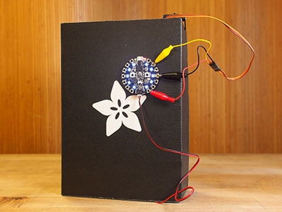
To develop this project further, you can easily connect a relay with a lock connected to it (see the schematic below).
Watch the video!
Also, check out this tutorial: Arduino Nano Matrix Keypad With Visuino
Learn more about Visuino: What is Visuino
What You Will Need
Arduino UNO (Or any other Arduino)
2X 1K ohm resistors
Visuino program: Download Visuino
Optional: A Relay


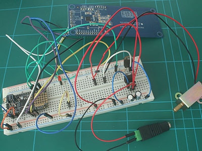
The Circuit
Connect Keypad pin 1 to Arduino digital pin 2
Connect Keypad pin 2 to Arduino digital pin 3
Connect Keypad pin 3 to Arduino digital pin 4
Connect Keypad pin 4 to Arduino digital pin 5
Connect Keypad pin 5 to Arduino digital pin 6
Connect Keypad pin 6 to Arduino digital pin 7
Connect Keypad pin 7 to Arduino digital pin 8
Connect Keypad pin 8 to Arduino digital pin 9
Connect Arduino pin [GND] to breadboard pin GND Line
Connect Arduino digital pin [11] to the breadboard Resistor1
Connect Arduino digital pin [12] to the breadboard Resistor2
Connect Resistor1 to the green LED's positive pin [+]
Connect the Green LED negative pin [-] to the breadboard pin GND Line
Connect Resistor2 to Red LED positive pin [+]
Connect the red LED negative pin [-] to the breadboard pin GND Line
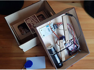
To add a relay and a solenoid:
Connect Relay VCC pin(+) to Arduino 5V pin
Connect Relay GND pin(-) to Arduino GND pin or to breadboard pin GND Line
Connect Relay signal pin(S) to Arduino Digital pin 11
Connect power supply 12V (+) to solenoid red wire(+)
Connect power supply 12V (-) to solenoid pin(com)
Connect solenoid black wire (-) to relay pin(NO)


Start Visuino, and Select the Arduino UNO Board Type
Start Visuino as shown in the first picture. Click on the "Tools" button on the Arduino component (Picture 1) in Visuino. When the dialog appears, select "Arduino UNO" as shown in Picture 2


In Visuino, Add Components
Add "Keypad" component
Add "Char Multi Source" component
Add "Char To Text" component
Add "Compare Text Value" component
Add "Toggle(T) Flip-Flop" component
Add 2X "Delay" component


In Visuino Set Components
Double-click on "Keypad1" and in the "Keys" window, drag "Character Key Group" to the left side. In the properties window, select "Keys" and click on the 3-dot button. Now, in a "Keys" window, drag 16X "Char Key" to the Left side, and for each key set "Character" in the properties window, set "Character" for each in the order as you see in picture 6, for
"Char Key1" the "Character" will be 1
for "Char Key2" the "Character" will be 4
for "Char Key3" the "Character" will be 7
for "Char Key4" the "Character" will be *
for "Char Key5" the "Character" will be 2
and so on until the end
Close All the Windows
Select "Delay1" and in the properties window, set "Interval (uS)" to 5000000
Select "Delay2" and in the properties window, set "Interval (uS)" to 5000000
Select "CharToText1" and in the properties window, set "Update On Each Char" to True
To Set the Keypad Code: Select "CompareValue1" and in the properties window set the "Value"; in this example, it is 34571


In Visuino Connect Components
Connect Arduino Digital Pin[6] to "Keypad1" > Rows Pin [0]
Connect Arduino Digital Pin[7] to "Keypad1" > Rows Pin [1]
Connect Arduino Digital Pin[8] to "Keypad1" > Rows Pin [2]
Connect Arduino Digital Pin[9] to "Keypad1" > Rows Pin [3]
Connect "Keypad1" > Columns Pin [0] to Arduino Digital Pin[2]
Connect "Keypad1" > Columns Pin [1] to Arduino Digital Pin[3]
Connect "Keypad1" > Columns Pin [2] to Arduino Digital Pin[4]
Connect "Keypad1" > Columns Pin [3] to Arduino Digital Pin[5]
Connect "Keypad1" > "CharacterKeyGroup16" pin [Out] to "CharMultiSource1" pin[In]
Connect "CharMultiSource1" pin [0] to "CharToText1" pin [In]
Connect "CharMultiSource1" pin [1] to "Delay1" pin [Start]
Connect "Delay1" pin [Out] to "CharToText1" pin [Clear]
Connect "CharToText1" pin [Out] to "CompareValue1" pin [In]
Connect "CharToText1" pin [Out] to "Delay2" pin [Start]
Connect "CompareValue1" pin [Out] to "TFlipFlop1" pin[Set]
Connect "Delay2" pin [Out] to "TFlipFlop1" pin[Reset]
Connect "TFlipFlop1" pin [Out] to Arduino Digital Pin[11]
Connect "TFlipFlop1" pin [Inverted] to Arduino Digital Pin[12]


Generate, Compile, and Upload the Arduino Code
In Visuino, at the bottom, click on the "Build" tab, make sure the correct port is selected, then click on the "Compile/Build and Upload" button.

Play
If you power the Arduino module, the red LED will glow, and if you enter the correct code, the green LED will glow for 5 seconds. If you do not enter the right code, the entered code will reset in 5 seconds, and you can try it again.
Congratulations! You have completed your project with Visuino. Also attached is the Visuino project that I created for this. You can download it here and open it in Visuino: https://www.visuino.eu