Scheme It
Schematic drawing and block diagramming made easy
Scheme It is an online schematic and diagramming tool that allows anyone to design and share electronic circuit diagrams. The tool includes a comprehensive electronic symbol library and an integrated DigiKey component catalog that allows for a wide range of circuit designs. Additionally, a built-in bill of materials manager is provided to keep track of parts used in a design. Once a schematic drawing is complete, users can export it to an image file or share it via email with others. We are Beta testing an export to KiCad for schematics. Scheme It works natively in all major web browsers without requiring the use of any plugins. You only need to be a registered user if you want to share and save designs.
Features
- Ability to diagram at the Block, Icon, System, or Schematic level.
- A library of over 700 generic symbols, as well as custom symbol creation.
- Access to over 4 million components via DigiKey Catalog integration.
- Freedom to keep designs private, make public, share via link, or embedded into web pages, blogs or emails.
- Rapid design evolution via Bill of Material (BOM) import capability.
- Integrated Bill of Materials and quoting.
- Export into PDF or PNG files and now other tools.
- A direct link to DigiKey Technical Support for help with component selection activities.
- Export functional schematic to KiCad design software
Related Videos
FAQs
Scheme It is a freely available tool customers can use as much as they like without charge. There is no Scheme It ‘license’, and you can use it to design schematics, flow charts, diagrams, and anything else they need for your business or any projects you might have without any legal entanglements. So long as you don’t try and sell access to Scheme It yourself, you should be good to go.
Scheme It is free to use in any customer’s browser and can be accessed easily from DigiKey’s website. Unfortunately the program cannot be downloaded for use offline; it runs in an Internet-enabled browser off of our servers.
Unfortunately, there is currently no way to change the color of a wire in Scheme It. Wire can be labeled the same way any other part can be labeled, but it cannot be recolored.
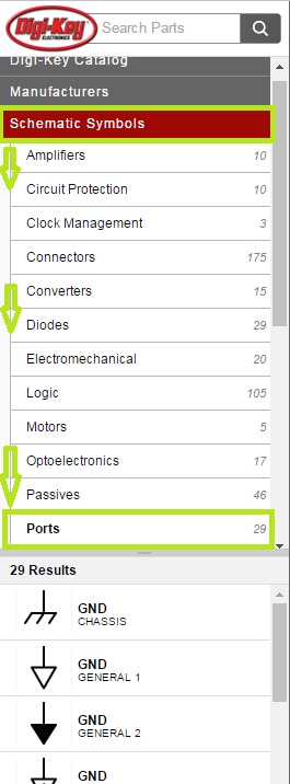
In Scheme It, Ground is considered a port. Go to Schematic Symbols > Ports, and you’ll have your pick of several Ground options.

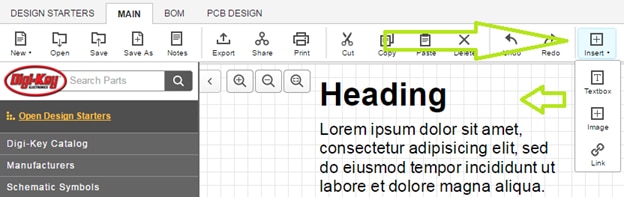
There are two ways to do this. In the topmost toolbar, right next to the Undo/Redo curvy arrows, there’s an ‘Insert’ drop-down key. You can use this key to insert pictures, web links, and text boxes in your schematic, all of
which can be resized and moved around as needed like any other part. Currently, the Insert method brings up a text box with the word “HEADING” followed by a bunch of Latin. If you see Latin, you’ve got it right.
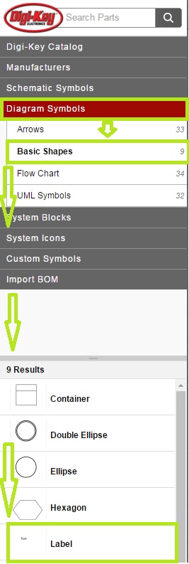
There’s also a ‘Label’ item in Diagram Symbols > Basic Shapes, which acts much the same way as the ‘Insert’ text box, without the Latin. Again, the label can be moved and resized as needed.

There’s also a ‘Label’ item in Diagram Symbols > Basic Shapes, which acts much the same way as the ‘Insert’ text box, without the Latin. Again, the label can be moved and resized as needed.

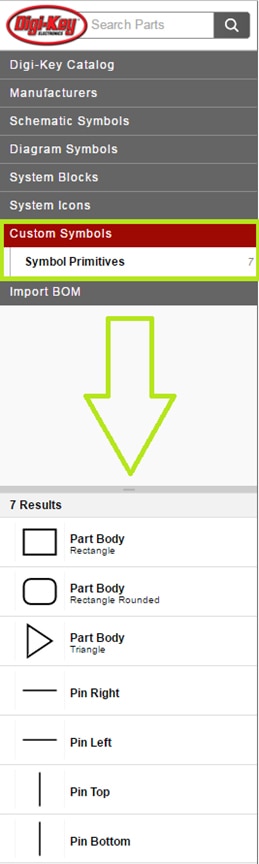
Most specific ICs don’t have their own individual icon you can drop onto schematics in Scheme It. What you can do instead is build your own IC with the custom symbol system. Go to Custom Symbols > Symbol Primitives, and you’ll
see different shapes of Part Body, as well as Top/Bottom/Left/Right legs. The body can be dragged onto the schematic, and the legs can be dragged onto the appropriate spots on the custom part body. Using this system, you can build most any IC schematic symbol you should need.

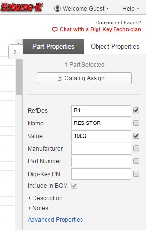
For any given object in Scheme It, there’s a Properties menu with tabs relevant to that object on the right-hand side of the program’s interface. Electronic devices can be named, given reference numbers, and have their values
adjusted, as well as having areas to specify manufacturer, MPN, DKPN, and other useful little tools. Things such as labels or flowchart blocks can have their font and colors adjusted, as well as being resized or flipped around as required.

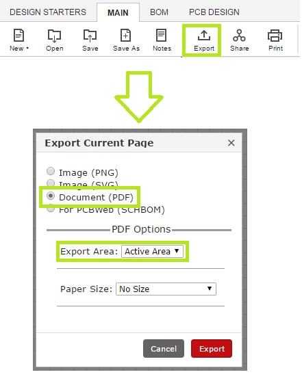
Printing directly from Scheme It is not currently advised, unless your circuit is large enough to use Scheme It’s entire drawable space. Instead, we recommend exporting your schematic as a PDF and printing from that. Starting with the ‘Export’ command in the top toolbar of Scheme It, you set the export type to “Document (PDF)”, and in the PDF Options, you set the Export Area drop-down menu to “Active Area”. This results in a PDF document with just your circuit on it and not the rest of Scheme It’s drawable area, perfect for printing.