Onderdeelnr. fabr. 28009
EXPERIENTIAL ROBOTICS PLATFORM (
SparkFun Electronics
Microcontrollers Arduino Raspberry Pi MCU Raspberry Pi SBC
In this final episode of our ROS 2 tutorial series, we bridge the gap between the ROS software world and real-world hardware. While ROS 2 offers an incredibly flexible and modular framework for robotics development, it does not directly interact with low-level hardware components like motors, sensors, or actuators. That’s where microcontrollers come into play. In this tutorial, we’ll demonstrate how to set up a communication channel between a ROS 2 node running on a Raspberry Pi and an Arduino-compatible microcontroller to control a simple robot.
The Docker image and code for this series can be found here: https://github.com/ShawnHymel/introduction-to-ros
One of the design goals of ROS is to provide a middleware architecture that scales. It excels at node orchestration, communication, data abstraction, and integration of complex components like SLAM, navigation, and perception. However, for tasks that require precise timing or real-time control, like generating PWM signals or handling sensor interrupts, general-purpose operating systems like Linux fall short. These tasks are better handled by microcontrollers, which can meet tight timing constraints.
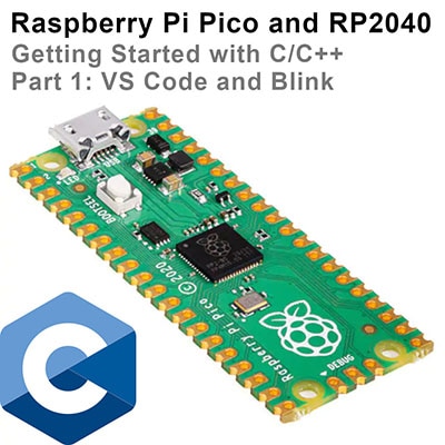
As such, the common robotics architecture is to have ROS running on a single-board computer (SBC), such as a Raspberry Pi, or a full, multi-board computer, which handles high-level tasks, and to delegate time-sensitive, low-level control to a connected microcontroller.
micro-ROS is a lightweight variant of the Robot Operating System (ROS 2) designed specifically for resource-constrained microcontrollers. It brings many of the core ROS concepts (e.g., nodes, topics, and services) into the embedded world by integrating with real-time operating systems (RTOS) like FreeRTOS or Zephyr. micro-ROS works by deploying a minimal ROS 2 client library onto the microcontroller, which then communicates with the larger ROS graph via a dedicated "agent" running on a host system. This agent handles coordination and message bridging between the microcontroller and the ROS 2 ecosystem.
micro-ROS is ideal when you want the microcontroller to participate directly in the ROS graph, for example, publishing sensor data, subscribing to actuator commands, or exposing services without writing custom communication bridges. However, its setup can be complex, requiring familiarity with embedded toolchains and RTOS environments. For many robotics applications, especially in education or rapid prototyping, it's often simpler to use a standard microcontroller with dedicated firmware and communicate with ROS nodes using UART, I2C, or other protocols. Choose micro-ROS when tight ROS integration on the embedded side is essential; otherwise, use traditional firmware when timing and simplicity are more important.
In this tutorial, we will stick to the simpler architecture of running ROS on the SBC that communicates to a microcontroller over serial via USB. As micro-ROS is complex and requires a good deal of setup, it is best saved for a future tutorial series.

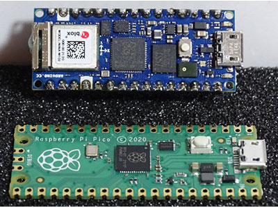
For this demonstration, we’ll use:

The Raspberry Pi acts as the ROS 2 host, and the Pico serves as the low-level motor controller. Communication happens via a USB serial connection.
You can find the CAD files for the custom battery and Raspberry Pi cage here: https://github.com/ShawnHymel/ros2-demo-ball-follower. Note that this repository also contains code for a ball-follower demo. One ROS node captures images from the Pi Camera, uses OpenCV to compute the bounding box (position, width, and height) of blue objects, and publishes that bounding box.
We start by writing a simple firmware in Arduino C++ that listens to serial commands and adjusts motor speeds accordingly. Using the Arduino-Pico core by Earle Philhower, we configure the Pico to listen for commands of the form:
<left_speed>, <right_speed>, <left_direction>, <right_direction>\n
These values are parsed, and corresponding pins are toggled to control the direction and PWM signal for the motors. This gives us a straightforward, deterministic motor control layer.
Here's a summary of what the Arduino firmware does:
This firmware is designed to be robust and minimal, ideal for direct motor control via a serial command protocol.
Enter this code into the Arduino IDE:
/**
 * XRP Serial Drive
 *
 * Send strings over serial (115200 baud rate) in CSV format:
 *
 *  "<left speed>, <right speed>, <left dir>, <right dir>\n"
 *
 * Speed is 0..100. dir is 0 or 1
 *
 * License: 0BSD https://opensource.org/license/0bsd
 */

// Settings
#define DEBUG 0
const int min_speed = 90;
constexpr int max_chars = 64;
constexpr int max_vals = 4;

// Pins
const int mt_l_dir_pin = 35;
const int mt_l_pwm_pin = 34;
const int mt_r_dir_pin = 32;
const int mt_r_pwm_pin = 33;

// Buffers
char input_buf[max_chars];
int vals[max_vals];
int buf_idx = 0;

void parse_csv_ints(char* input) {
  byte val_count = 0;

  // Break string apart based on delimiter
  char* token = strtok(input, ", ");

  // Save values and continue breaking apart string
  while (token != NULL && val_count < max_vals) {
    vals[val_count++] = atoi(token);
    token = strtok(NULL, ", ");
  }
}

void setup() {

  // Configure serial
  Serial.begin(115200);

  // Configure drive pins
  pinMode(mt_l_dir_pin, OUTPUT);
  pinMode(mt_l_pwm_pin, OUTPUT);
  pinMode(mt_r_dir_pin, OUTPUT);
  pinMode(mt_r_pwm_pin, OUTPUT);

  // Don't move
  analogWrite(mt_l_pwm_pin, 0);
  analogWrite(mt_r_pwm_pin, 0);

  // Initialize values array
  memset(vals, 0, sizeof(vals));
}

void loop() {

  // Receive bytes from serial
  while (Serial.available() > 0) {

    // Read and parse the line-terminated string
    char received = Serial.read();
    if (received == '\n') {
      input_buf[buf_idx] = '\0';
      parse_csv_ints(input_buf);
      buf_idx = 0;
    }
    else if (received != '\r' && buf_idx < max_chars - 1) {
      input_buf[buf_idx++] = received;
    }
  }

  // Debug received message
#if DEBUG
  Serial.print("Parsed values: ");
  for (int i = 0; i < max_vals; i++) {
    Serial.print(vals[i]);
    if (i < max_vals - 1) Serial.print(", ");
  }
  Serial.println();
#endif

  // Set motor directions
  int l_dir = vals[2] > 0 ? 1 : 0;
  int r_dir = vals[3] > 0 ? 1 : 0;
  digitalWrite(mt_l_dir_pin, l_dir);
  digitalWrite(mt_r_dir_pin, r_dir);

  // Calculate motor speed: map 1..100 to min_speed..255
  int l_speed = vals[0] > 0 ? vals[0] : 0;
  int r_speed = vals[1] > 0 ? vals[1] : 0;
  if (l_speed > 0) {
    l_speed = map(l_speed, 1, 100, min_speed, 255);
  }
  if (r_speed > 0) {
    r_speed = map(r_speed, 1, 100, min_speed, 255);
  }

  // PWM signal is inverted in reverse
  if (l_dir == 1) {
    l_speed = 255 - l_speed;
  }
  if (r_dir == 1) {
    r_speed = 255 - r_speed;
  }

  // Set motor speeds
  analogWrite(mt_l_pwm_pin, l_speed);
  analogWrite(mt_r_pwm_pin, r_speed);
}
Upload the code to the XRP board. Note that you will need to hold the BOOT button, press and release the RESET button, then release the BOOT button to put the RP2350 into bootloader mode.
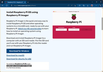
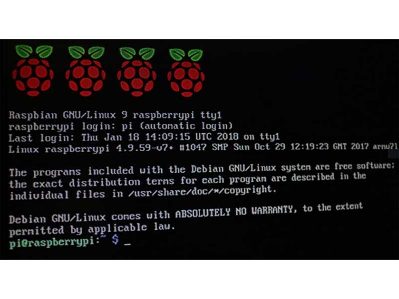
On the Raspberry Pi, flash Ubuntu 24.04 and install the necessary packages:
sudo apt update
sudo apt install -y net-tools openssh-server python3.12-venv python3-pip
Enable SSH so you can log into the Pi remotely:
sudo systemctl enable ssh
sudo systemctl start ssh
Install ROS 2 Jazzy, set up a Python virtual environment, and add pySerial:
python3 -m venv venv --system-site-packages
source venv/bin/activate
python3 -m pip install pyserial
Add your user to the dialout group so you can use the serial port without sudo:
sudo usermod -a -G dialout $USER
Enable the ROS 2 environment (you can also add this line to the end of ~/.bashrc):
source /opt/ros/jazzy/setup.bash
Create a workspace (in the pibot_ws workspace folder) and initialize the package:
mkdir -p ~/pibot_ws/src
cd ~/pibot_ws/
colcon build
cd src/
ros2 pkg create --build-type ament_python pibot_pkg
Set up the Python virtual environment. Note that before running your node, you should initialize the Python virtual environment and then initialize the ROS environment for your package. The COLCON_IGNORE file tells the colcon build system to ignore the venv folder.
cd ..
python3 -m venv venv --system-site-packages
 touch venv/COLCON_IGNORE
source venv/bin/activate
Install Python packages:
python3 -m pip install pyserial
We now create a Python ROS 2 node called driver_demo that periodically sends drive commands to the microcontroller over USB serial.
This node:
Here is a snippet of how the drive command is formatted:
self._serial_port.write(
 f"{left_speed}, {right_speed}, {left_dir}, {right_dir}\n".encode()
)
The node runs in a timer loop and simulates simple autonomous behavior without requiring external sensors or input. Add the following code to pibot_ws/src/pibot_pkg/pibot_pkg/driver_demo.py:
import rclpy
from rclpy.executors import ExternalShutdownException
from rclpy.node import Node

import serial

class DriverDemo(Node):
    """Move the robot around some"""

    def __init__(self):
        """Constructor"""
        super().__init__('driver')

        # Declare parameters
        self.declare_parameter('serial_port', '/dev/ttyACM0')
        self.declare_parameter('baud_rate', 115200)
        self.declare_parameter('timeout', 1)

        # Initialize serial port
        self._serial_port = serial.Serial(
            port=self.get_parameter('serial_port').value,
            baudrate=self.get_parameter('baud_rate').value,
            timeout=self.get_parameter('timeout').value
        )

        # Set up state machine to drive around
        self._state = 0
        self._timestamp = self.get_clock().now()

        # Periodically call method
        self._timer = self.create_timer(0.1, self._driver_callback)

    def _driver_callback(self):
        """Drive around"""

        # Increment state
        elapsed = self.get_clock().now() - self._timestamp
        if elapsed.nanoseconds > 1e9:
            self._timestamp = self.get_clock().now()
            self._state += 1
            if self._state >= 3:
                self._state = 0
            self.get_logger().info(f"State: {self._state}")

        # Set speed and direction based on state
        if self._state == 0:
            left_speed = 25
            right_speed = 50
            left_dir = 0
            right_dir = 0
        elif self._state == 1:
            left_speed = 100
            right_speed = 100
            left_dir = 1
            right_dir = 0
        else:
            left_speed = 0
            right_speed = 0
            left_dir = 1
            right_dir = 0

        # Send commands to the robot
        self._serial_port.write(
            f"{left_speed}, {right_speed}, {left_dir}, {right_dir}\n".encode()
        )
        self._serial_port.flush()

def main(args=None):
    """Main entrypoint"""

    # Initialize and run node
    try:
        rclpy.init()
        node = DriverDemo()
        rclpy.spin(node)
    except (KeyboardInterrupt, ExternalShutdownException):
      pass
    finally:
        if node is not None:
          node.destroy_node()
        if rclpy.ok():
          rclpy.shutdown()

if __name__ == '__main__':
    main()
Add the rclpy dependency to package.xml:
<license>TODO: License declaration</license>
<depend>rclpy</depend>
Add the executable to setup.py:
"driver_demo = pibot_pkg.driver_demo:main",
Build the package:
 cd ~/pibot_ws
colcon build --packages-select pibot_pkg
With the Arduino firmware flashed to the RP2350, use a USB cable to plug the XRP board into the Raspberry Pi. Connect the battery to the Raspberry Pi. You can SSH into the Pi or use a keyboard, mouse, and monitor to launch the ROS node. You will need to initialize the Python virtual environment (to get access to the pyserial library) and the pibot_pkg package environment:
cd ~/pibot_pkg
source venv/bin/activate
source install/setup.bash
ros2 run pibot_pkg driver_demo
The robot should start driving around in a (mostly) square pattern!

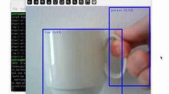
To demonstrate the power of combining ROS with microcontroller control, we also built a vision-based object follower using OpenCV. A separate ROS 2 node processes frames from a Pi Camera and identifies a blue object. The node publishes bounding box information to a topic, and a subscriber node translates that into serial commands to drive the motors.
This creates a fully integrated robot with visual feedback that can follow a blue ball, stop when it's close, or back up if the ball gets too near. This is a great example of high-level computation (OpenCV) paired with real-time control (microcontroller). You can find the custom CAD design for the battery and Raspberry Pi, Arduino firmware, and ROS node code here: https://github.com/ShawnHymel/ros2-demo-ball-follower
While ROS 2 doesn’t talk to hardware directly, it excels at managing high-level logic, coordination, and perception. By delegating real-time control to microcontrollers and establishing a communication link (e.g., serial, I2C, CAN), we can build powerful and responsive robotic systems. This modularity is what makes ROS so scalable.
Thanks for following this ROS 2 tutorial series. We hope you now feel confident integrating real hardware with your ROS applications.
Happy hacking!